Early historical developments
The history of multi-body dynamics (MBD) goes back to at least the Bronze Age when the Sumerians in Mesopotamia devised wheels by sticking solid axles through wooden discs. The use of these wheels to move carts/chariots provided the first example of a multi-body vehicle system. The history of the wheel, having been famously reinvented more than 50,000 times, parallels the developments of other mechanisms such as sextants, clocks, cam-followers, bearings, pistons, gears, etc. Most inventions and redesigns come about as the result of a need or an idea, not because of deliberate premeditation and scientific/analytical rigour.
Analysis and design evaluation is a relatively new endeavour since the sixteenth century and the trials of the polymaths such as Galileo Galilei (1564–1642). In those days, analyses were based on perspectives, geometry as an extension of movements of planets, and a form of synthesis in which Galileo excelled with his designs of machines and mechanisms. He followed in the footsteps of his fifteenth Century predecessor Leonardo Da Vinci (1452–1519). Leonardo proposed inventions such as his self-drive car (“vehicle”) and ornithopter
1; these being the first examples of multi-body systems in the Middle Ages. However, unlike all the previous polymaths, Galileo understood the concept of force and moment, as in centrifugal force and couple and other basic kinetics. Therefore, Galileo laid down the scientific foundation for the mechanical perspective.
2,3In Galileo's time, much of the dynamic analysis was based on observation, now termed as kinematics, which is the measurement of observed phenomena without regard to the underlying cause. It was observed by Kepler in 1609
4 that all the planets in the solar system revolve around the Sun in elliptical orbits of low eccentricity on the ecliptic plane (the Heliocentric system). This enunciation by Kepler and then Galileo put paid to the favoured ecclesiastical Earth-centred universe proposed by Aristotle (384–322 BC). In any case, the first observed multi-body system (the Solar system) engaged the attention of many in the ancient times through to the Middle Ages.
5,6The motions of planets around the Sun, as kinematic observations, were published in 1609 as Kepler's three laws of motion.
4 In 1687, Isaac Newton
7 showed that the elliptical planetary motions described by Kepler's laws conform to the underlying dynamics established by Newton's own three laws of motion and that of his law of universal gravitation. With the establishment of rigid body dynamics and its application to planetary motion, Newtonian mechanics was born, together with a proper description of the concepts of force and gravitation. Hence, planetary motion in the solar system became the first thoroughly investigated multi-body system.
Large displacement-low-frequency vehicle dynamics (ride and handling)
In the case of vehicle engineering, MBD analysis was initially applied to vehicle ride and handling studies. It has been progressively used with larger degrees-of-freedom (DOF) systems for vehicle suspension analysis in industry using such computer codes as Automatic Dynamic Analysis of Mechanical Systems (ADAMS) and Dynamic Analysis and Design System (DADS). These codes provide automatic generation of differential-algebraic equations (DAE) and their simultaneous solution. Therefore, they are suitable for use in industry primarily for constrained rigid body dynamics, typically of suspension kinematics/dynamics, vehicle ride comfort analysis and vehicle manoeuvres/handling/road holding. Within the spectrum of dynamics’ phenomena, such applications may be classified as large displacement low-frequency events.
MBD studies were initially used for ride comfort and/or vehicle handling by Segel
15 and McHenry.
16 Other early applications of multi-body theory for vehicle dynamics were included.
17–20 With the advent of detailed multi-body codes, large DOF vehicle models were developed with practical complex nonlinear suspension systems, and with the inclusion of tyre models
21–27 for vehicle handling analysis. Complex manoeuvres were presented including lane-changes, slalom motions, J-turns, and cornering and braking.
27–29 Hegazy et al.
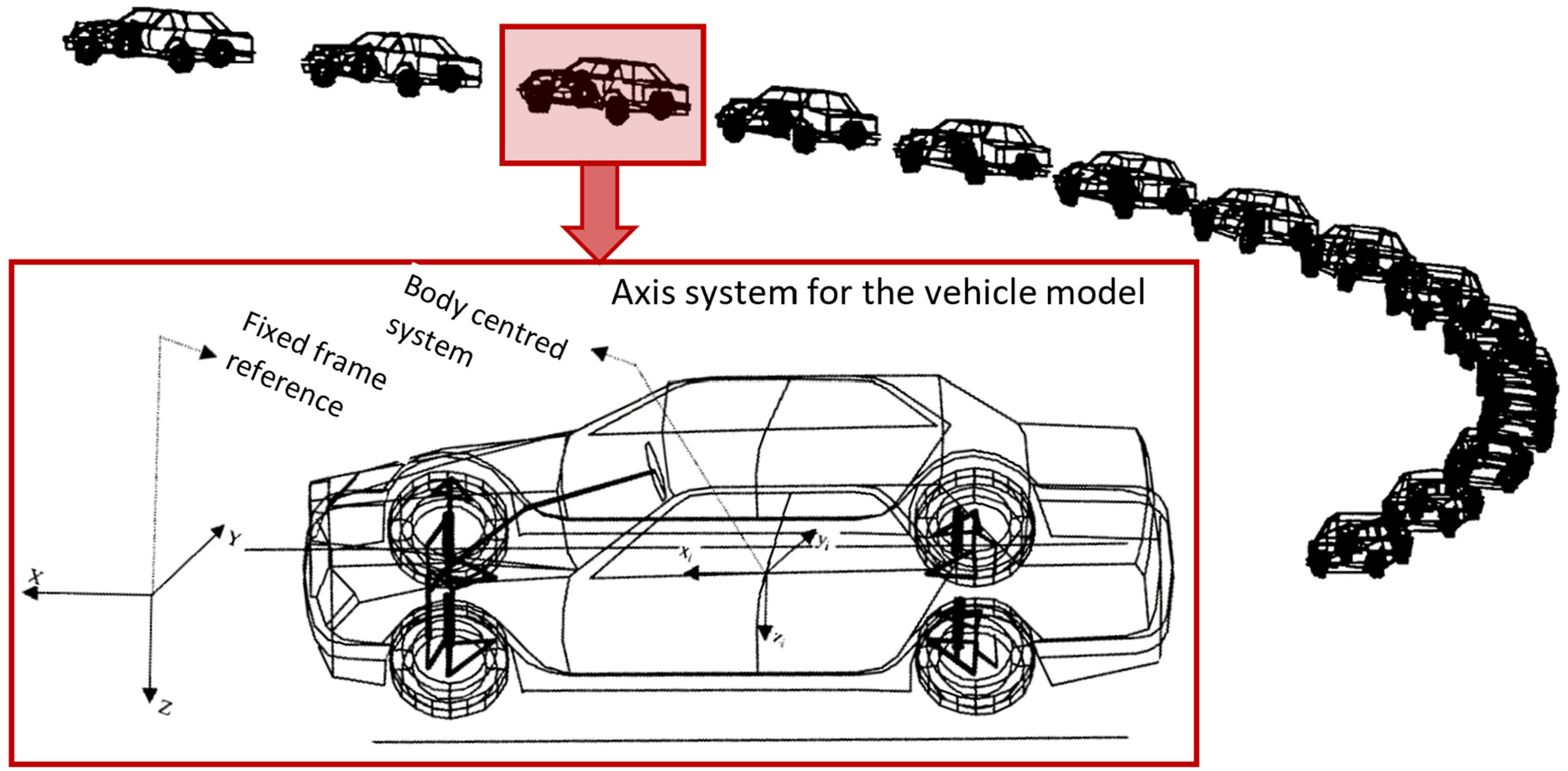
27 presented a 94 DOF full-vehicle model and subjected it to various manoeuvres for assessment of vehicle handling in line with international standards such as International Standard Organisation and British Standard (BS).
Figure 1 shows the modelled vehicle undertaking a lateral transient manoeuvre specified by BS AU 230.
30 Other researchers have considered various vehicle control features such as four-wheel steer (4WS) and Direct Yaw Control.
31,32Nowadays, multi-body analysis plays an important role in the development and design evaluation of vehicles and their sub-systems. Such analyses include suspension kinematics and dynamics, elasto-kinetics, as well as vehicle ride comfort and road holding.
19,33,34 Increasingly, a large number of additional load-case scenarios (other than those stated above) are taken into account in vehicle development. These include bounce, pitch and roll in traversing over road calming features (bumps), negotiating single bump events or falling into potholes.
35–39 Harsh conditions such as kerb strike
40 are also considered. von Chappuis et al.
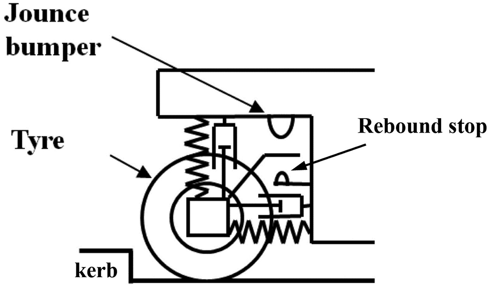
40 showed that a simple 7 DOF vehicle dynamics model would suffice for drive-over-kerb studies at various kerb strike speeds of up to 40 kph and for different kerb heights. The model included experimentally verified jounce bumper and rebound stop characteristics (
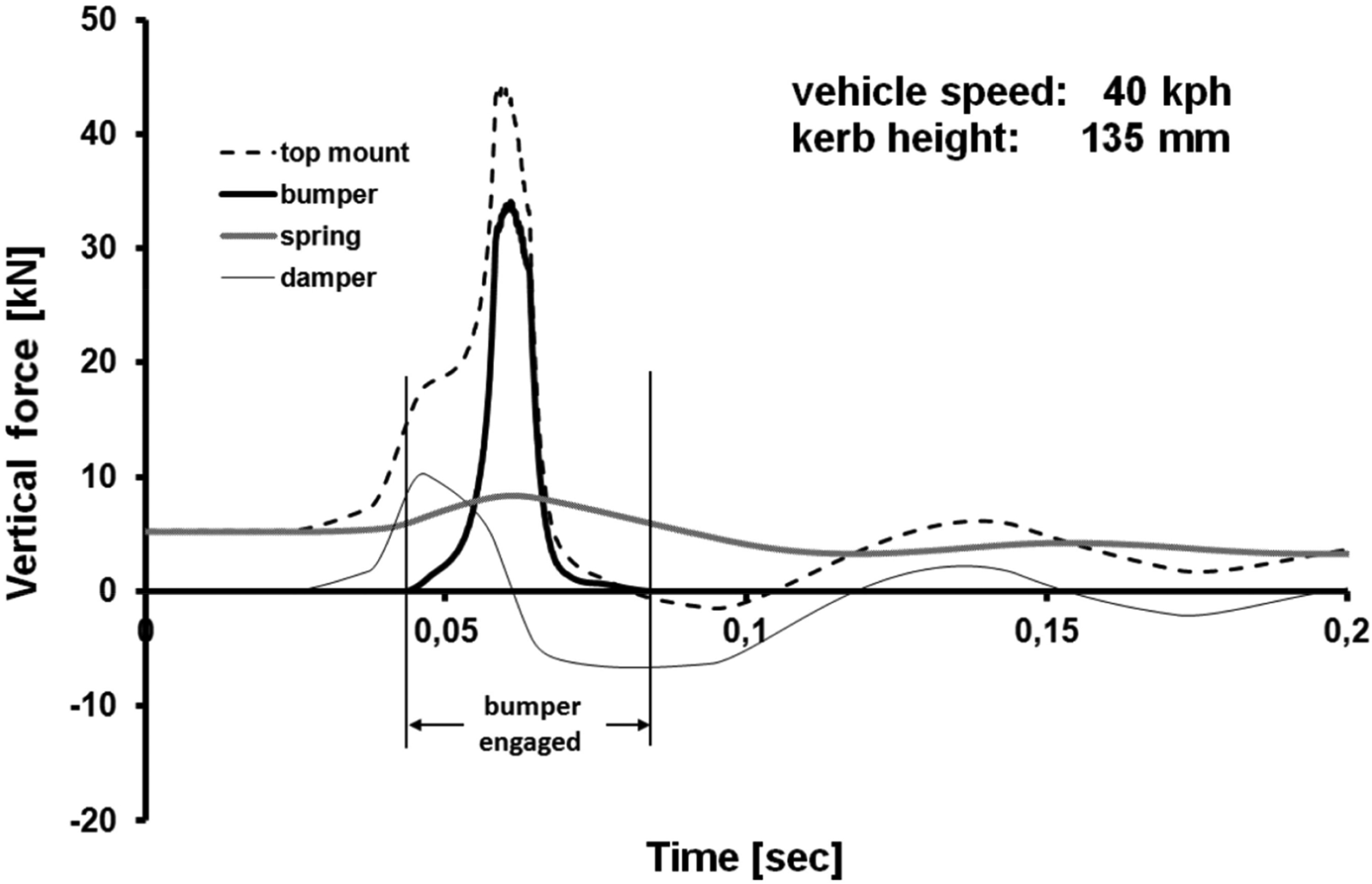
Figure 2). The non-linearity and hysteresis of polymeric structures of jounce and rebound stops were included using experimentally verified mapping characteristics rather than the usual approach of simplified representations, using various viscoelastic analytical models. Therefore, fairly accurate prediction of vertical impact reactions of tyres, suspension mounts, jounce bumper and rebound stops were obtained (
Figure 3). Such studies can help the design of chassis and suspension elements’ characteristics.
All these load-case scenarios affect kinematics of suspension, the applied forces acting on the chassis and suspension elements, as well as their structural integrity. Therefore, they can be used for design and design analysis of suspension systems’ structures, their integrity and control.
41–46 All these studies necessitate the inclusion of detailed tyre models and elasto-kinetics of suspension compliance.
Two main types of tyre models have been developed. One is empirical, based on ever-increasing physical testing with purpose-built rigs, detailed testing procedures, data acquisition and regression analysis. Such empirical models lead to the creation of analytical expressions for tyre forces in terms of an increasing number of governing parameters/conditions. Good reviews of tyre modelling and testing procedures have been provided.
47–51 Among the physical tyre models, the Magic-Formula tyre model is the most widely used.
49The other type of tyre model is based on fundamental principles of contact mechanics with discretised elemental representation, relating the tyre reaction to localised deformation of the chosen element type. The elements usually include a small mass with stiffness and damping characteristics.
47,52–57 These elements are generally termed brush elements and may have various elastic or viscoelastic characteristics. Some of these tyre models have been extended to include the effect of tyre carcass elasticity and inflation pressure.
56–59 These additional features make the models more suitable for transient vehicle dynamics with combined slip, cornering and braking under extreme conditions, as well as riding over obstacles and kerb strikes.
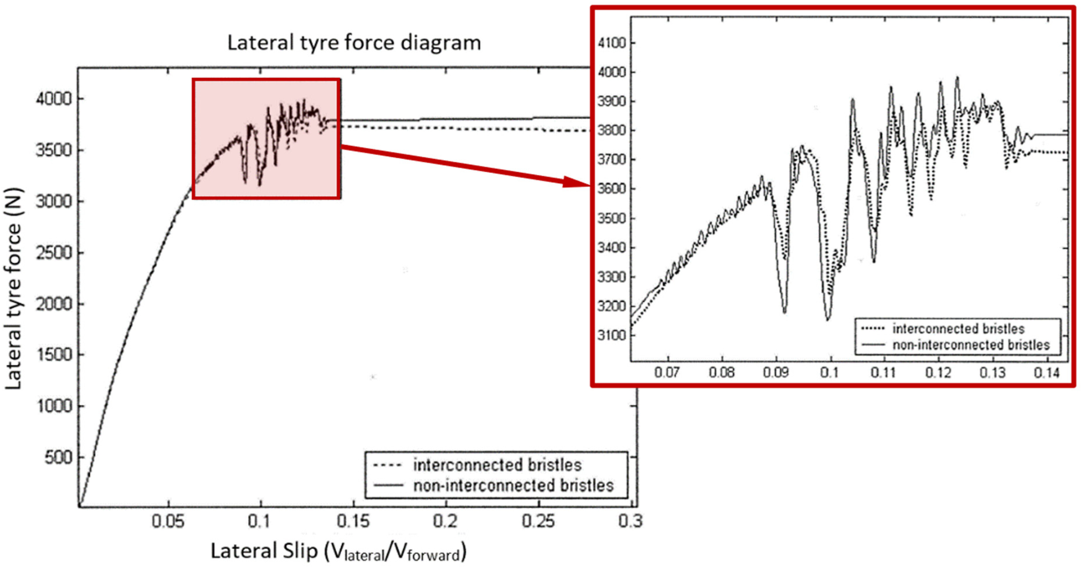
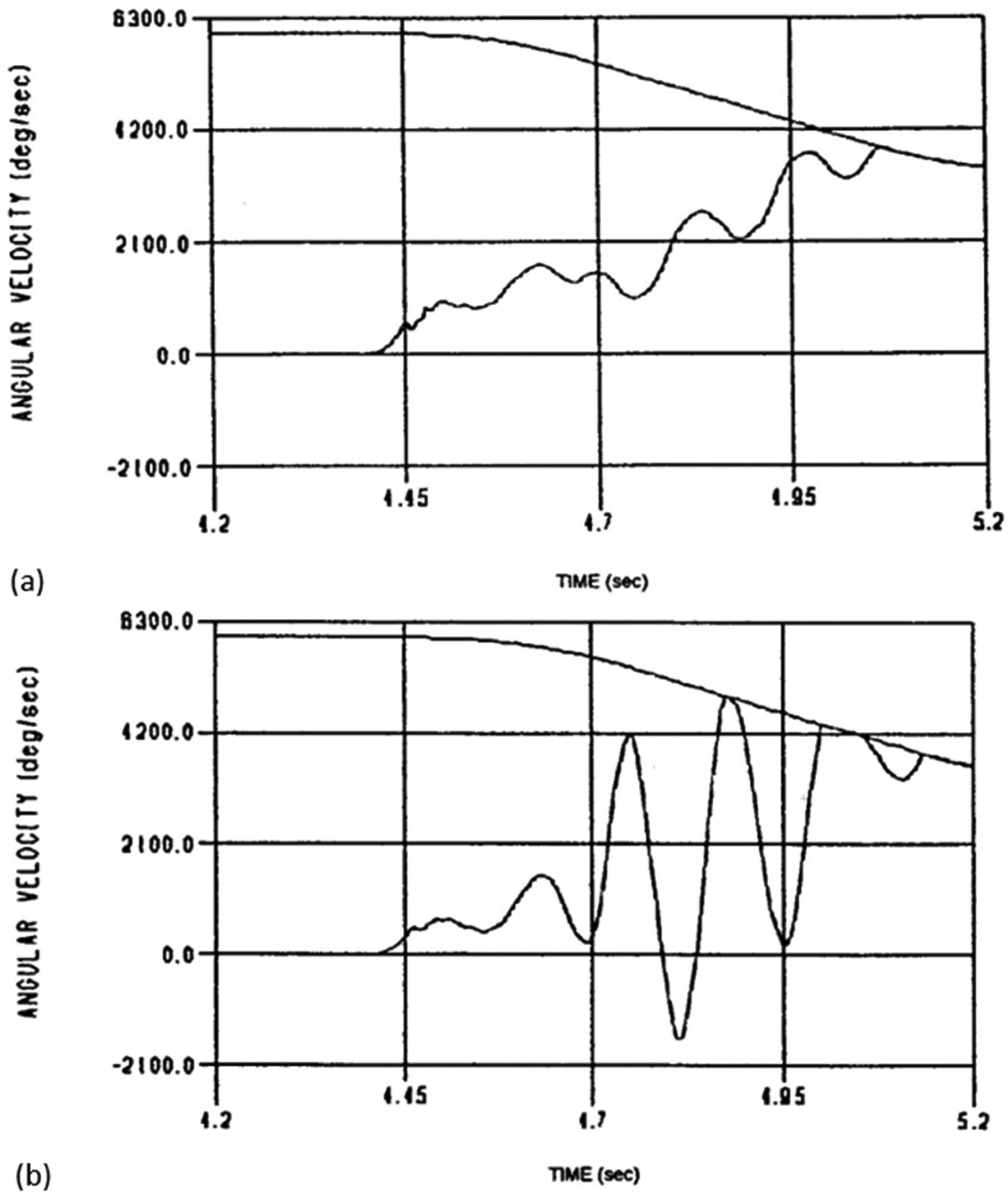
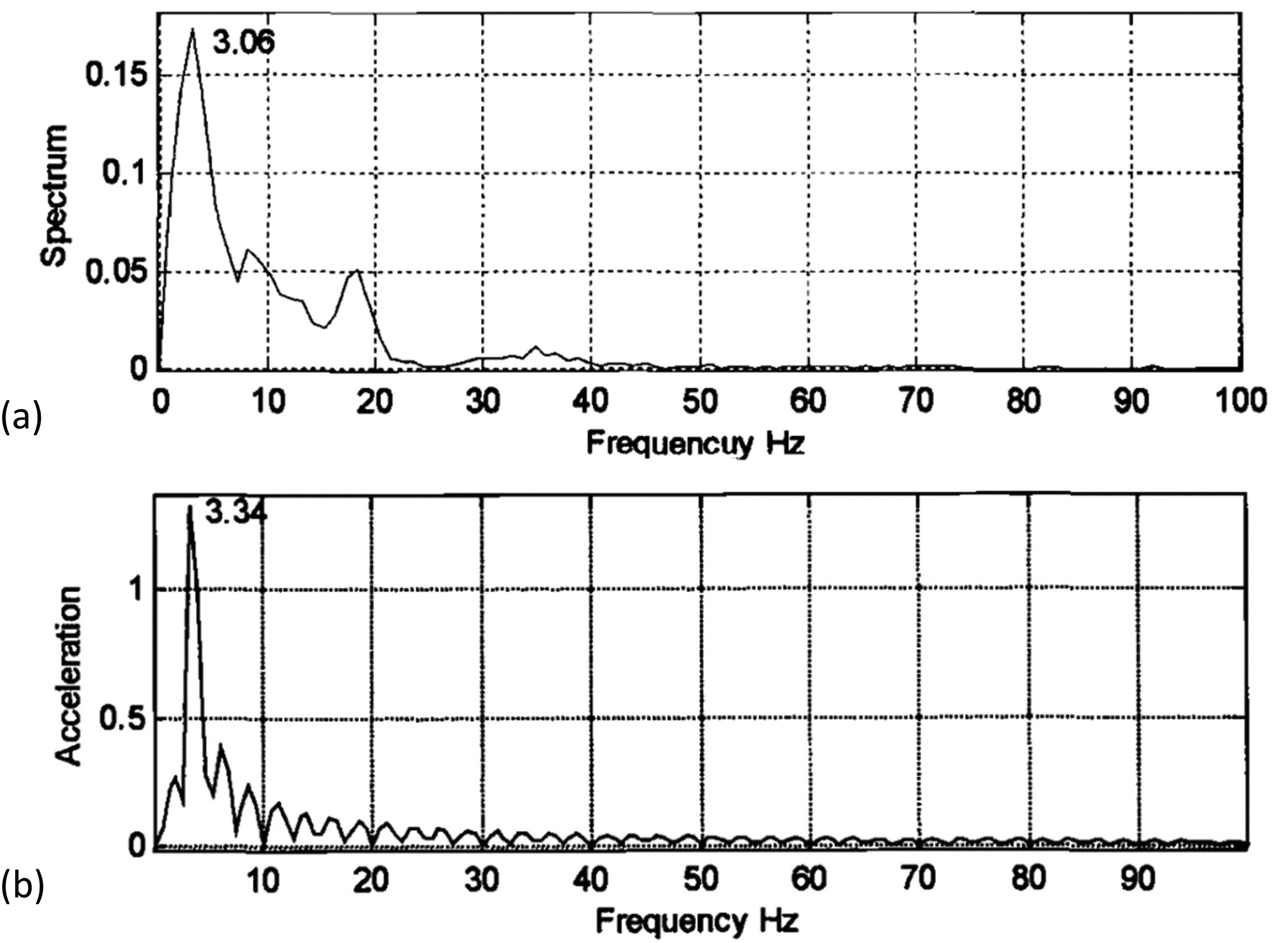
Figure 4 (a) and (b) show two types of brush models. In both cases, the tyre belt is discretised into small masses in contact with the road surface. Each element is an anisotropic bristle with carcass stiffness and damping properties which may follow any assumed viscoelastic model or simply use measured maps. To improve response characteristics under transient conditions, tyre belt behaviour is represented by elemental interconnections as shown in
Figure 4(b).
Figure 5 shows that brush models with belt interconnections better capture the response of the tyre, shown by the fluctuations evident at the onset of any transient manoeuvre. Soft materials such as tyres undergo creep even in rolling with slip, which sets up a transient response. Creep under slip stretches the tyre belt so that its periphery appears to be longer. This effect is captured by belt interconnections in the model of
Figure 4(b). Belt, carcass and bead flexibility have also been included in some widely used empirical physical tyre models.
60,61 Friction can be implemented between the small-discretised masses and the road surface in order to represent tyre-paved road contact in the case of brush-type models. Coefficient of friction (rolling resistance) can be estimated based on an iterative recursive solution, or stick-slip motion, or different road surface topography, as well as on any changes in environmental conditions.
53–55,62–67 Therefore, conditions leading to slipping can be investigated for vehicles travelling over terrains with some wheels running on unmade road verges, or ice or snow. Such conditions cause drag or slip, and are referred to as split-µ.
68 They can cause directional stability issues and tyre transience, when steering and braking, that require various control systems such as anti-blocking braking system, and 4WS.
69–73Off-road vehicles often run on soft and deformable surfaces (unprepared terrain). A detailed analytical method was proposed by Bekker
74,75 for the parametric analysis of off-road vehicle performance. The most important aspect of off-road vehicle dynamics is the inclusion of pertinent tyre models. Soil sinkage under a wheel is caused by two independent effects: the pressure-sinkage orthogonal to the soil surface, and shear-tension-displacement along the direction of a rolling wheel (ruttage). Terramechanical tyre-soil interaction include either phenomenological analytical models with viscoelastic or poroelastic representation of the soil, or numerical models using finite element analysis.
76–82 Various studies with off-road multi-body vehicle dynamics have been carried out on different soft soils such as sand and loam. This is in order to improve the tractive efficiency and optimisation of drivetrain components such as differentials and visco-lock systems.
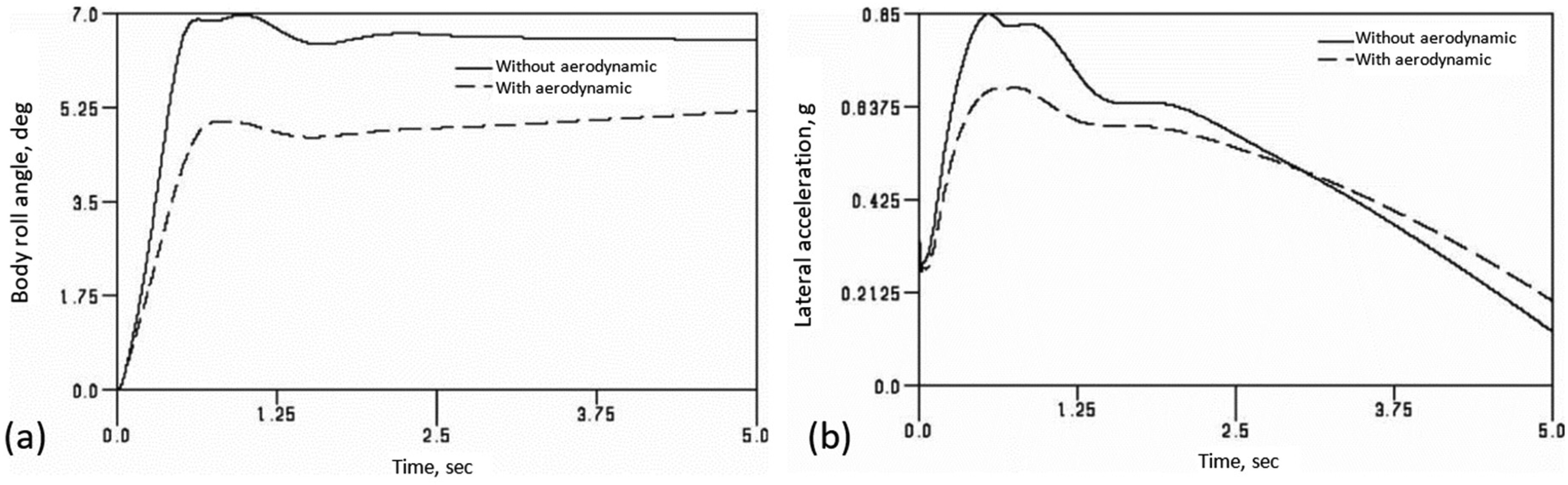
79,83–87Within the area of vehicle handling, some other features can include the effect of aerodynamic forces (lift and drag), as well as unsteady conditions such as crosswind and side gusts.
88–94 Hussain et al.
90 used the same detailed 94 DOF full-vehicle model in
27 to study the same cornering manoeuvre, but with the introduction of aerodynamic forces. The lift and drag characteristics of the vehicle were obtained using a 10% physical scale model placed in a wind tunnel prior to analysis using Computational Fluid Dynamics (CFD). The aerodynamic and multi-body vehicle handling co-simulation was compared with the same vehicle manoeuvre without the inclusion of aerodynamic action. Most modern saloon vehicles corner up to a lateral acceleration of 0.8 g, during which a body roll angle of
-
occurs.
Figure 6(a) shows the body roll during the cornering manoeuvre with and without the inclusion of aerodynamic forces. In both cases the body roll increases prior to reaching the corner and levels-off after the corner has been negotiated. During such a manoeuvre, body weight transfer occurs from the inside to the outside wheels. It can be seen that the aerodynamic lift reduces the lateral weight transfer. One practical implication of such studies is that aerodynamic forces improve the vehicle stability in such motions with reduced lateral acceleration for the same manoeuvre as is shown in
Figure 6(b).
Other additions to multi-body vehicle dynamic analysis have included vehicle occupants in the form of realistic human dummies/humanoids or more detailed biomechanical human skeletal models. These have been used for studies ranging from ride comfort to vehicle impacts. They also aid in the assessment of the performance of vehicle occupant safety features such as seatbelts and airbags by predicting physical injuries to occupants and pedestrians in different vehicle collision scenarios such as frontal, side or rear impacts. Representative literature for multi-body vehicle dynamics, including biomechanical issues are reported.
95–106Concluding remarks
The foregoing shows that MBD analysis entered the application domain with four main developments: (i) automatic generation of equations of motion, (ii) solution of generated DAEs, (iii) sparse matrix technology and (iv) improved step-by-step integration methods. These developments led to MBD analysis codes such as ADAMS and DADS, which were initially used by the automotive and aerospace industries. This article covers applications of MBD in vehicle engineering.
In vehicle engineering, the original widespread use of MBD has been in relatively large displacement dynamics (suspension analysis, ride comfort assessment and vehicle handling/road holding). Increasingly, the role of component flexibility in MBD analyses has become commonplace (elasto-kinetics of suspensions, impacts, etc). Therefore, elasto-MBD has embraced component flexibility with resulting infinitesimal vibrations (modern MBD analysis is carried out in a multi-scale manner). Furthermore, the use of MBD in powertrain analysis has resulted in the inclusion of other physical phenomena such as contact/impact dynamics, friction in microscale and generated heat. Thus, the state of the art in modern multi-body analysis has become multi-physical and multi-scale. Over the past 25 years, the Journal of Multi-body Dynamics (JMBD) has been at the forefront of many developments, some of which have been recalled and expanded upon in this artitlce.