Introduction
Carbon can form different allotropic structures composed entirely of carbon but with different physical and chemical structures, such as graphite, graphene, diamond, fullerene, carbon black (CB), graphite nanofiber (GNF), carbon nanotubes (CNTs), nanorings carbon (CNRs), and carbon nanospheres (CNSs).
1,2 Among these carbon allotropies, CNTs were found to be key nanomaterial because of their superior unique properties. Since Iijima. (1991)
3 found CNTs accidentally while synthesizing fullerene by arc discharge method, undoubtfully it became the headlines of nanotechnology due to their unique mechanical,
4,5 thermal, and electrical properties.
6,7 Recently, toroidal CNTs catch the attention of researchers because they can be used directly as a nanoscale device.
8 In the last 10 years, due to the enormous potential of CNS in the storage and conversion of energy, the synthesis of carbon spheres has attracted researchers.
9–15 Even some researchers have tried to combine the synthesis of CNTs, and/or CNSs, CNRs,
16 which may be possible by optimizing the process parameters. Moreover, the multi-layered fullerenes, also known as onion-like carbons or carbon nano-onions seem to promising in the biomedical applications.
17,18 Therefore, the purpose of this review is to update the knowledge on the use of chemical vapor deposition processes to synthesize carbon nanomaterials (such as CNT, CNR, and CNS).
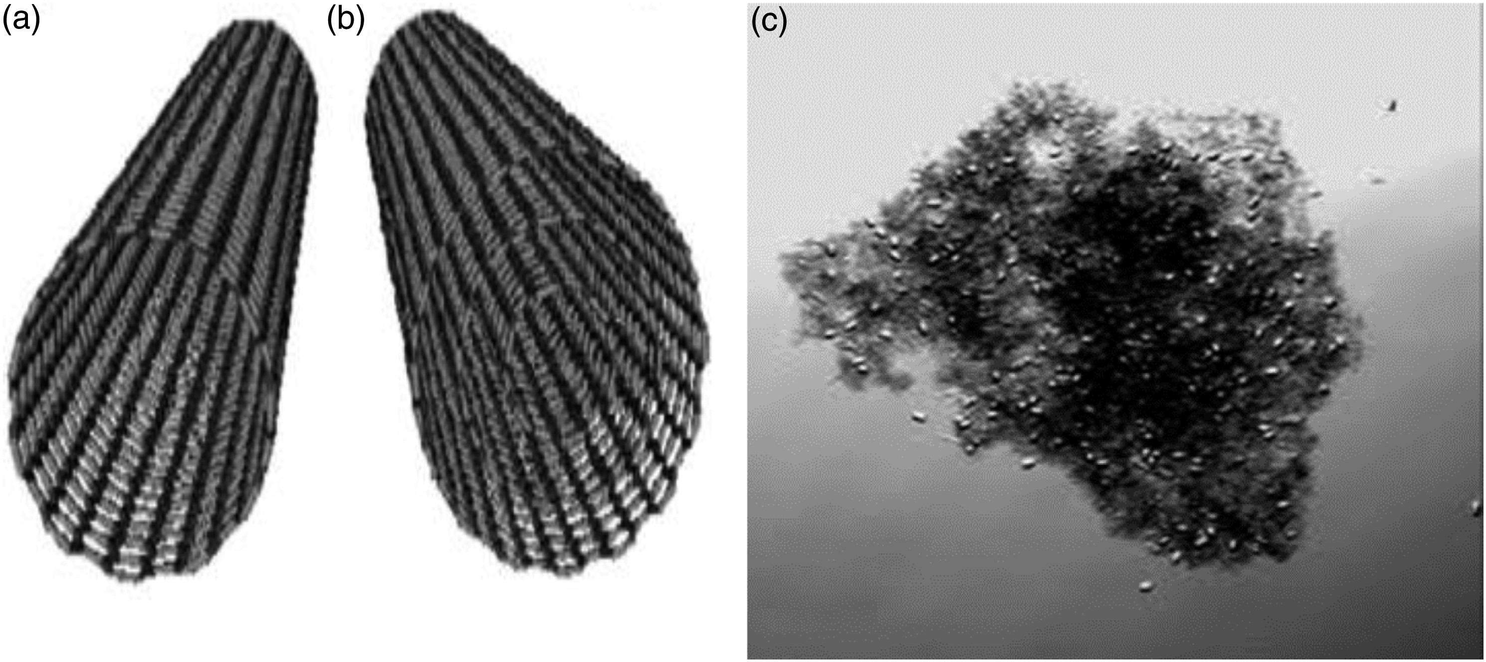
For the naked eye, CNTs will look like black charcoal powder (see
Figure 1(c)), but at higher magnification, they will be visible as cylindrical structures. If a single graphene sheet is rolled, it is called SWCNT (
Figure 1(a)) and multiple graphene sheets are rolled it is called MWCNT (
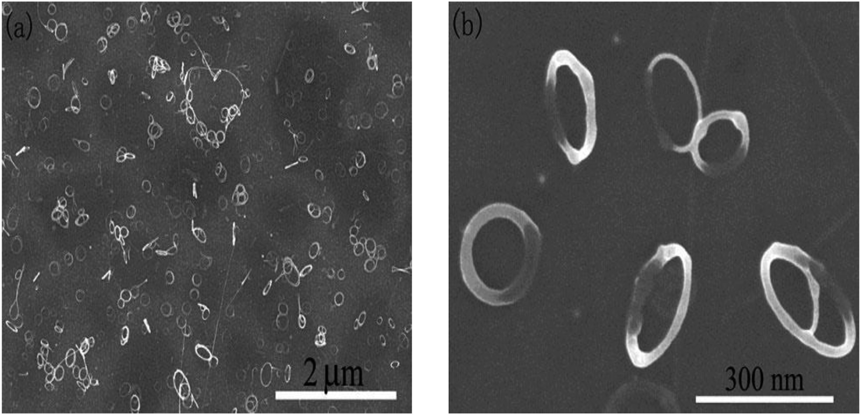
Figure 1(b)). If the CNTs are rolled as a ring, then it is called CNRs (
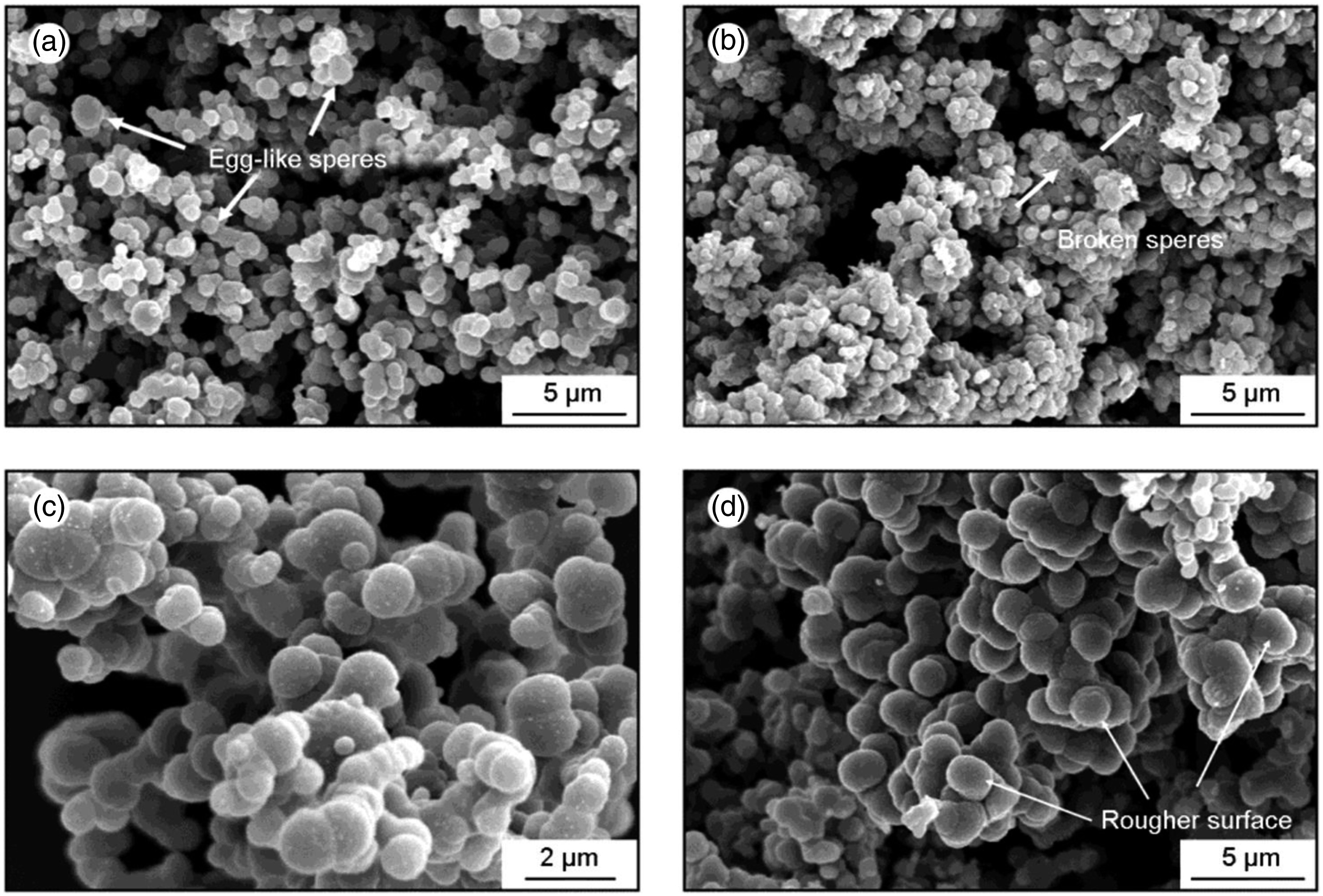
Figure 2). If the carbon forms like a football shape then it is called Carbon CNSs (
Figure 3).
There are many methods for synthesizing carbon nanotubes, including arc discharge, laser ablation, and chemical vapor deposition (CVD) processes. For a long time, arc discharge and laser ablation have been the primary methods for obtaining near-perfect single-walled carbon nanotubes and multi-walled carbon nanotubes. There are several questions about these methods. First, both methods rely on the evaporation of carbon atoms from a solid carbon source at 3000° C, which is not efficient and limits the amplification of CNTs. Second, the nanotubes synthesized by the evaporation method are in the form of entanglements, which are difficult to purify, manipulate, and assemble to build addressable nanotube structures.
21,22 The schematic diagram of the CVD process is shown in
Figure 4.
Compared to laser ablation and arc discharge methods, CVD is a simple and inexpensive technique for synthesizing CNTs at low ambient temperature and pressure. In terms of crystals, arc and laser grown carbon nanotubes are better than CVD grown carbon nanotubes. However, CVD outperforms arc and laser methods in terms of performance and purity. Also, CVD is the only answer when building the controller CNT architecture. CVD is versatile because it can use a large amount of hydrocarbons in any state (solid, liquid or gas), it can use a variety of substrates and it allows the growth of CNT in various forms, such as powder, thin or thick film, lined or entangled nanotubes, straight or coiled, or desired nanotube structures at predetermined locations on a patterned substrate. It can also better control growth parameters.
24 Table 1 shows a summary and comparison of the three most common CNT synthesis methods.
The main aim of this investigation is to review the literature (See
Table 2) on CNTs, CNRs, and CNSs synthesis via the CVD process.
Table 2 shows a list of articles that were published in the synthesis of different allotropies of carbon up to the year 2020. The criteria for this review paper include the type of CVD chamber, catalyst material used, type of carbon structure obtained, the effect of CVD process parameters like reaction temperature, the flow rate of a precursor gas, and reaction time were summarized.
Carbon nanotubes
The growth mechanism of carbon nanotubes has been controversial since their discovery. Based on CVD response conditions and purification analysis, some researchers have proposed more than a few often conflicting possibilities. Thus, until now, not even one CNT growth mechanism has been well established. On the other hand, the most common and widely accepted mechanism can be summarized as follows. When steam from the precursor gas comes into contact with the “hot” metal catalyst particles, it first breaks down the carbon atoms and hydrogen atoms, the hydrogen atoms fly away, and the carbon atoms dissolve into the catalyst metal. After reaching the solubility limit of the carbon atoms in the catalyst metal at this reaction temperature, the dissolved carbon begins to accumulate in the vertical direction. The decomposition of precursor gases (hydrocarbons) (as an exothermic process) releases some heat to the catalyst metal, while the crystallization of carbon (as an endothermic process) absorbs some heat from the catalyst metal precipitation zone
24.
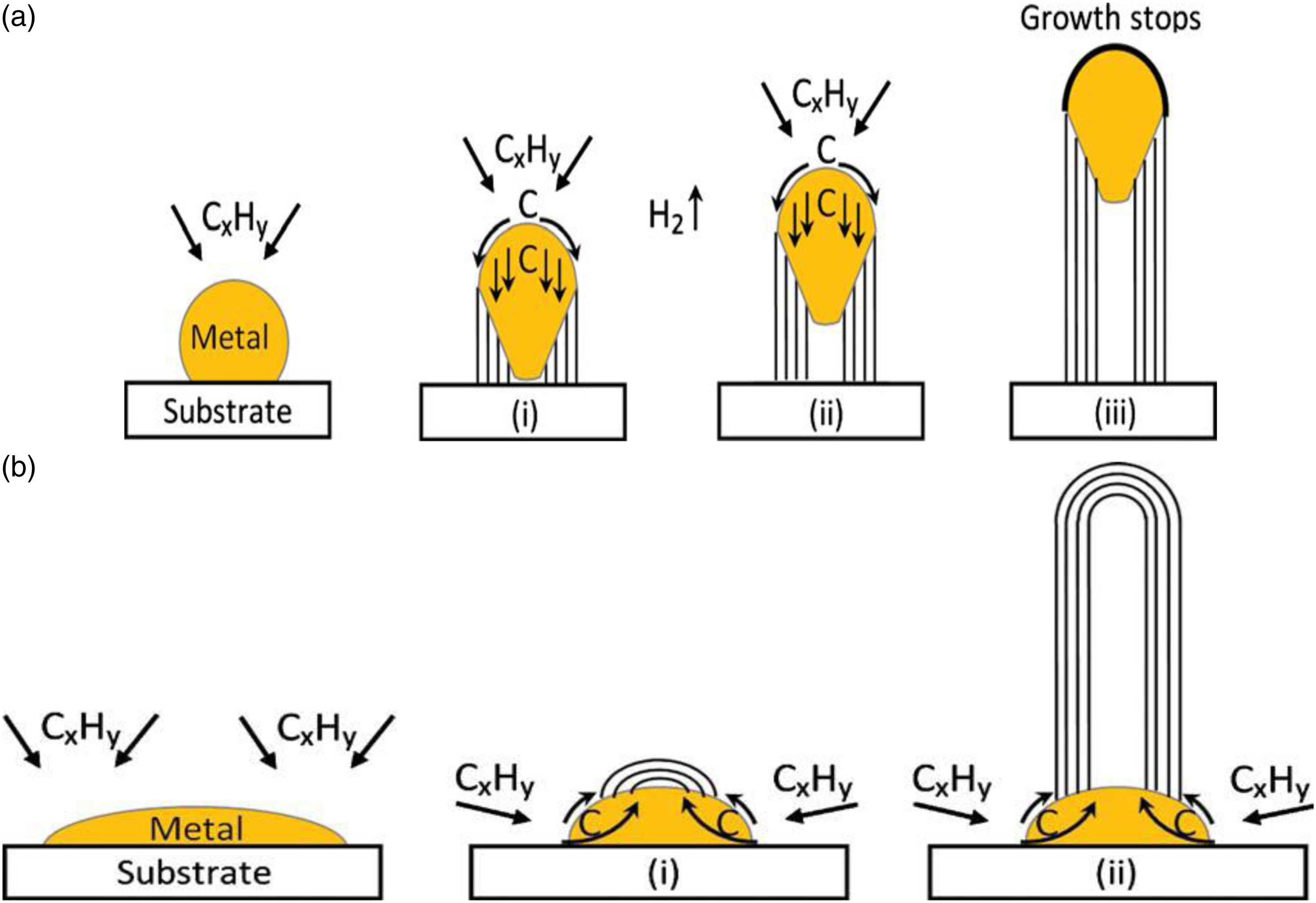
As shown in
Figure 5, there are two general cases, in case one (
Figure 5(a))
1.
When the catalyst-substrate interaction is weak, the precursor gas (hydrocarbon) decomposes on the upper surface of the catalyst metal, carbon diffuses downward through the catalyst metal, and CNTs precipitate through the bottom of the metal, expelling all metal particles. Substrate.
2.
As long as the top of the metal is open to the decomposition of fresh precursor gas, the CNT will continue to grow larger.
3.
Once the catalyst metal is completely covered by excess carbon atoms, its catalytic activity will stop and the growth of the carbon nanotubes will also stop, which is called the “tip growth model.”
43In the second case, (
Figure 5(b)) when the catalyst to substrate interaction is strong, initial hydrocarbon decomposition and carbon atoms diffusion take place similar to that in the tip-growth case, but the CNT precipitation fails to push the metal particle up; so the precipitation is forced to emerge out from the top of the catalyst metal.
1.
First, the carbon crystallizes into a hemispherical dome, and then extends upward into a seamless graphite cylinder.
2.
Subsequent deposition of hydrocarbons occurs on the lower peripheral surface of the catalyst metal and diffuses upward with the dissolved carbon atoms. Therefore, the catalyst particles take root at the bottom when CNTs grow; therefore, this is called the “base growth model.”
44Effect of CVD process parameters on CNTs growth
CNTs synthesized using the CVD process have various process parameters that control the final structure of CNTs.
30 Hence, in these section main CVD process parameters such as reaction temperature, the flow rate of a precursor gas, and reaction time and their effect on CNTs structure will be discussed.
Effect of temperature on CNTs growth
Researchers grown CNTs on Ni catalyst films using methane at 900°C show poor coverage (see
Figure 6) which may be due to the lack of nickel islands formed on the copper surface to catalyze the growth of CNT. The diameter of CNTs grown with a methane source is larger than that of carbon nanotubes grown with an acetylene source at a lower temperature. CNTs grown in acetylene at 650°C show better coverage and are smaller in diameter. Raman data also shows that the quality of CNTs grown is better using the acetylene source at 650°C. The authors concluded that acetylene is a better choice for large-scale synthesis of MWCNTs in copper using Ni catalytic film than methane.
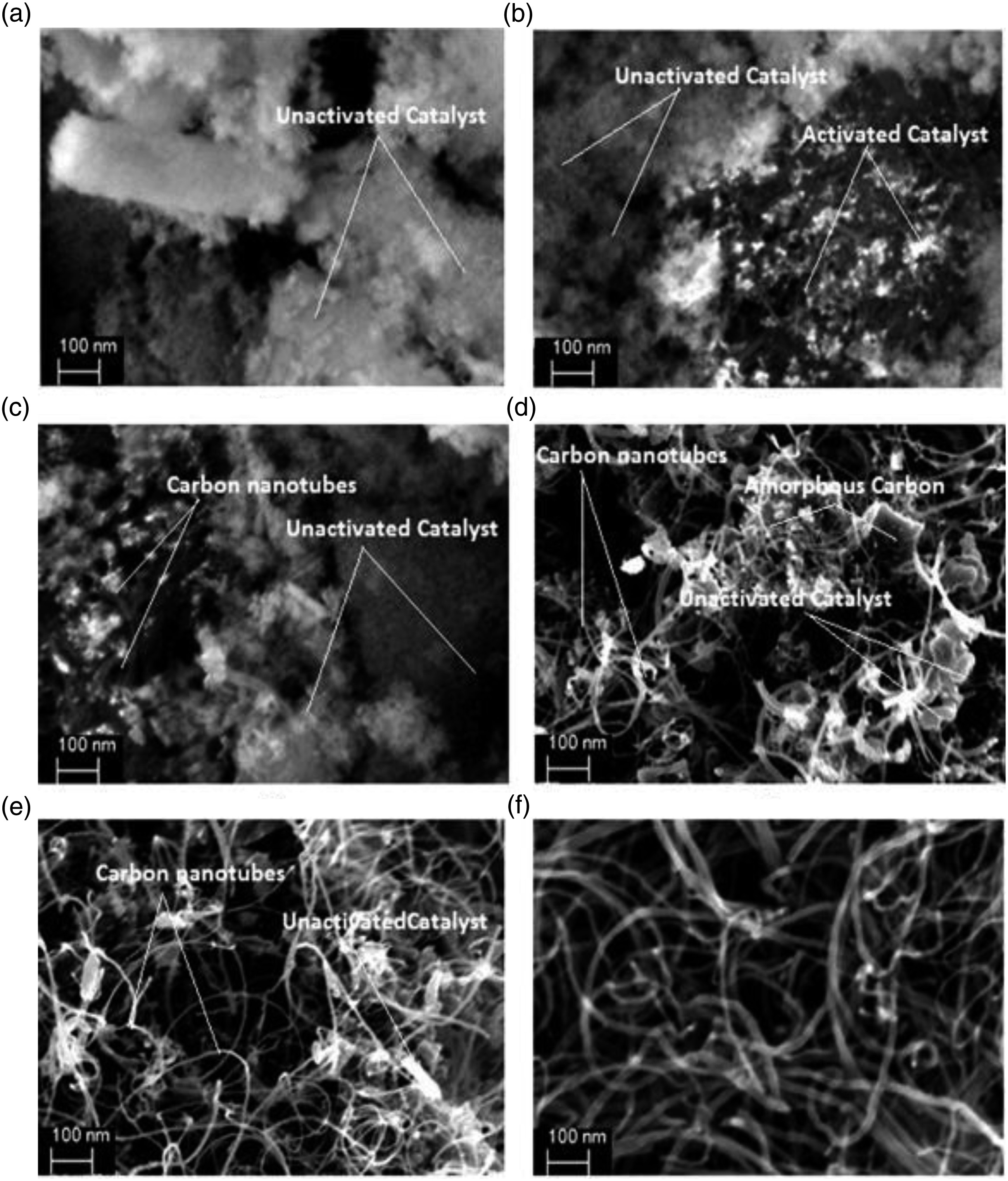
31Authors also reported the growth of carbon nanomaterials including CNTs and carbon onions were manufactured on nano-sized Ni/Al catalysts at 450–600° C using the CVD methane process (see
Figure 7). The author used transmission electron microscopy and X-ray energy dispersive spectroscopy to characterize carbon nanomaterials, and studied the influence of Ni/Al catalyst composition and reaction temperature on the morphology of carbon nanomaterials. The results showed that carbon nanotubes and carbon onions were synthesized at moderate temperatures. The composition of the Ni/Al catalyst and the reaction temperature has a great influence on the morphology of carbon nanomaterials. When a relatively high reaction temperature (550–600°C) and a relatively low nickel content (60% by weight) catalyst are used, pure carbon onions can be obtained.
45Effect of precursor gas flow rate on CNTs growth
Shukrullah et al. (2015)
46 conducted a systematic study on the optimization of the CVD process parameters to study the diameter distribution of the MWCNTs grown on Fe
2O
3/Al
2O
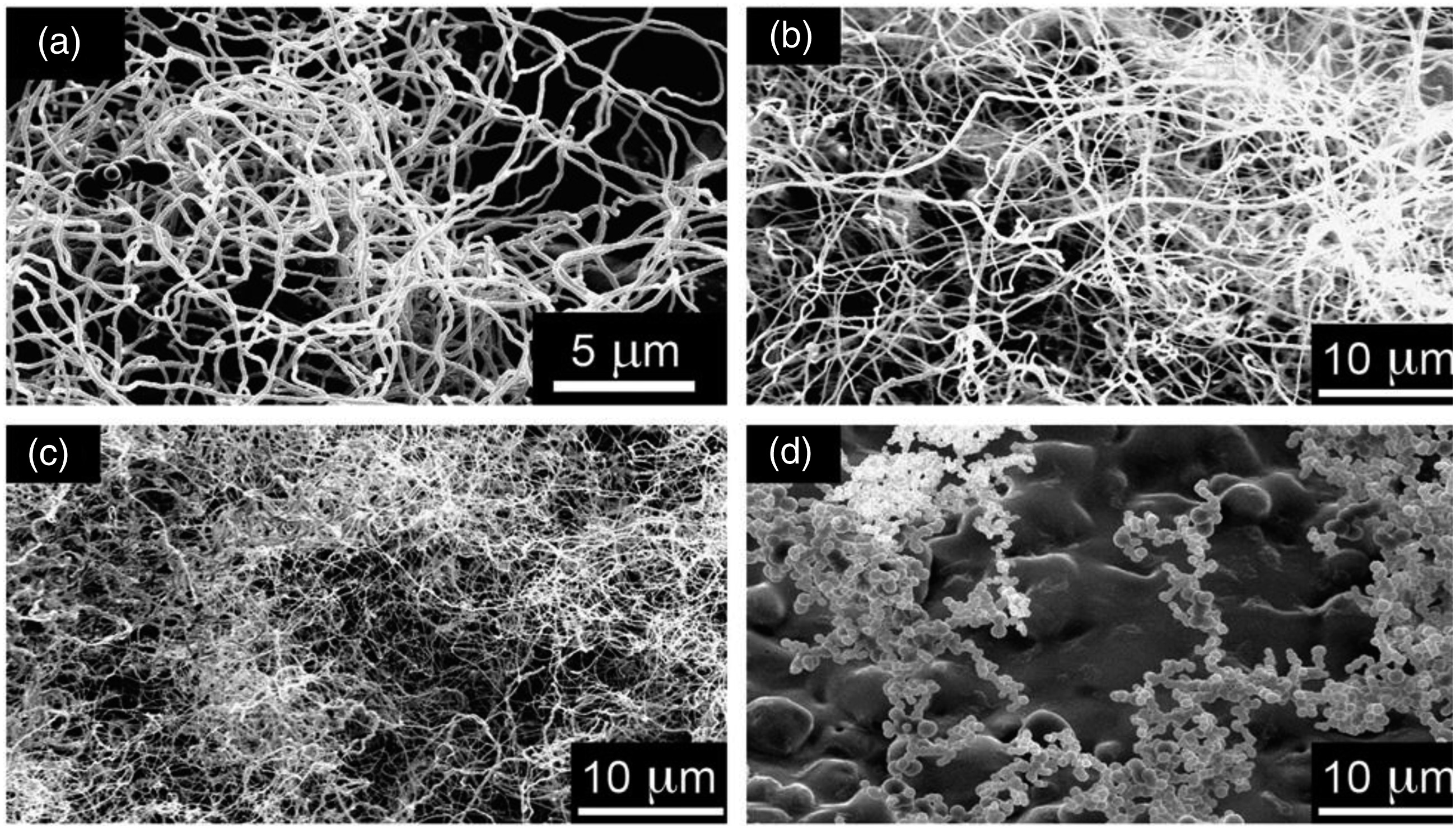
3 catalyst support at a fixed temperature of 800°C. FESEM and TEM techniques were used to quantify the influence of the flow rate of ethylene and the CVD process time in the CNT growth parameters. At a critical ethylene flow rate of 100 sccm and a CVD treatment time of 60 min, these studies observed dense and uniform growth of relatively pure nanotubes with a longer tube length and a narrow diameter distribution (see
Figure 8).
Under optimal conditions, the growth of carbon nanotubes has the narrowest diameter distribution, which is 20–25 nm. . Furthermore, under these operating conditions, the low surface defects and impurities, the high yield percentage and the graphite structure of the growth tube are obvious. In the optimized parameters of the CVD process, there is a balance between the decomposition rate of C2H4 and the diffusion rate of carbon in the Fe2O3/Al2O3 catalyst particles. The C2H4 flow rate is less than 100 sccm and there are not enough reactants (carbon atoms) to react with the metal particles to make the most of the available catalyst. Due to the lower availability of catalyst particles, when the flow rate is greater than the optimal value, the concentration of the carbon source will not significantly affect the decomposition or the growth rate of CNT.
Effect of process time on CNTs growth
According to Zhan et al., in 2007,
47 a high flow rate can prolong the residence time of the hydrocarbon gas on the catalyst surface, thus producing a good carbon nanotube structure (see
Figure 9). Furthermore, high precursor gas flow rates tend to increase the decomposition rate of hydrocarbons, resulting in higher yields of carbon products. Tripatti et al. 2014
32 studied the influence of acetylene flux and treatment time on CNT growth. It is observed that the performance and the length of the pipeline decrease linearly with the flow rate and the time of the precursor gas. Contradicting the above statement some authors reported that the morphology of carbon nanotubes does not depend on carbon feedstocks, especially when specific catalysts are used in the process.
48,49Influence of catalyst particles on CNTs growth
In order to synthesize CNTs using the CVD process, nano-sized metal catalyst particles are generally required to allow the decomposition of hydrocarbons at a temperature lower than the spontaneous decomposition temperature of hydrocarbons.
The most commonly used metals are Fe, Co, Ni because for two main reasons (see
Table 3):
1.
The high solubility of carbon in these metals at high temperatures; and
2.
The high diffusivity of carbon atoms in these metals. In addition, the high melting point and low equilibrium vapor pressure of these metals provide a wide CVD temperature window for various carbon precursors.
Researchers have conducted more experiments and used different types of transition metals as catalysts to find the suitable catalyst system to synthesize CNTs via CCVD process. Shin. et. al., (2006)
50 reported that reported that methane was used as a carbon source to synthesize CNTs and obtain MWCNTs in an Al-supported Ni catalyst. Sivakumar. et. al., (2011)
25 reported that used catalytic CVD process to synthesize multi-walled carbon nanotubes, using methane as the precursor gas and nickel as the metal catalyst. In this report, it was found that the Ni catalyst showed a methane conversion rate of 42%. Mendoza et al. 2005
51 synthesized MWCNT using a catalytic CVD process, and reported the influence of Co. Awadallah et al. 2012
26 synthesized CNTs by a CVD process using Ni-Mo-Al and Co-Mo-Al. In this report, the author has concluded that the Ni-Mo-Al catalyst gave higher purity of CNTs compared to the Co-Mo-Al catalyst. Tyagi et al., (2011)
27 CNTs synthesized using Cu grid, commonly used as TEM specimen support. In this report, the author concluded that the Cu does not seem to be suitable for CNTs growth. Kwszka et al., (2014)
28 reported that three different types of CVD, such as vertical, horizontal, and quartz tubes, were used to grow CNT using Cu thin films. In this report, the addition of additional sulfuric acid to the Cu catalyst film was found to promote CNT growth.
The researchers also used bimetallic catalysts to synthesize carbon nanotubes through a CVD catalytic process. Li et al. 1997
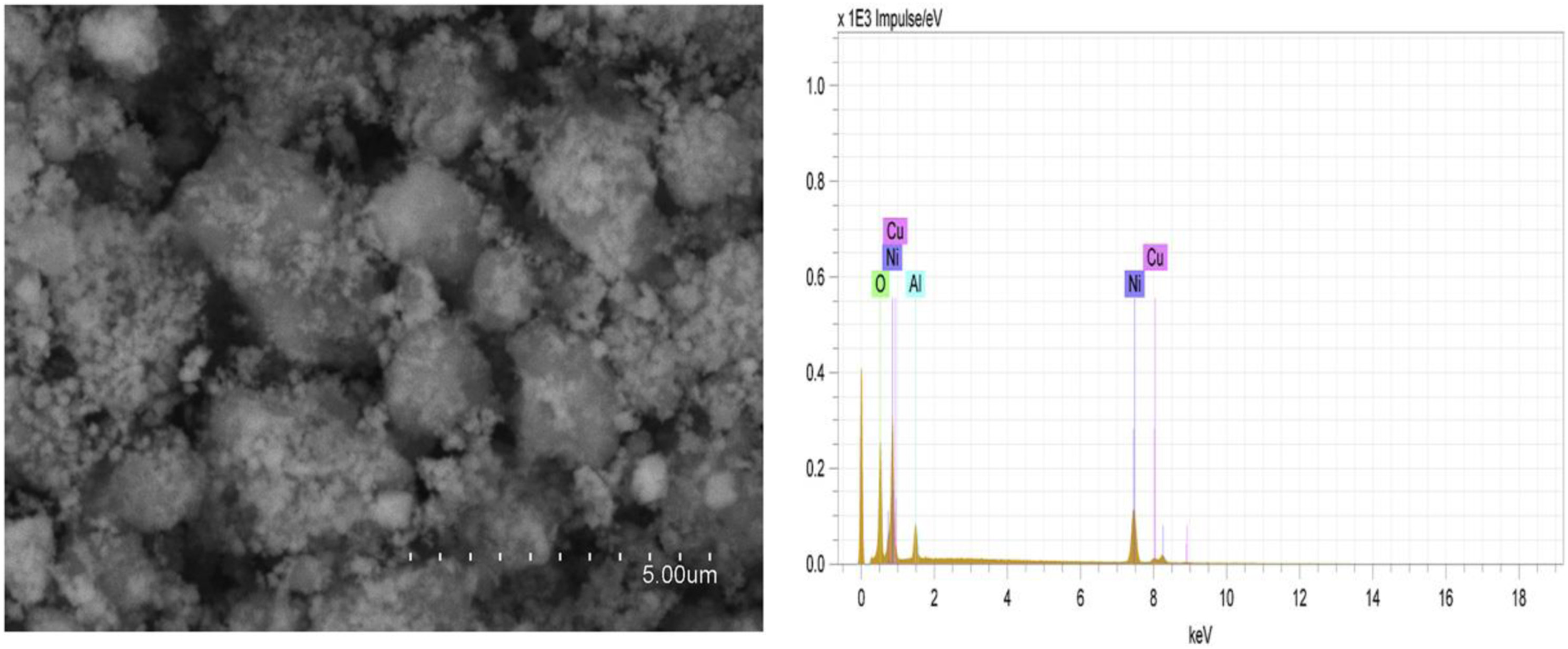
52 used Ni/Cu/Al catalysts to synthesize CNTs through a catalytic CVD process, and reported that the addition of Cu to Ni particles improves the catalytic growth efficiency of CNTs. Pinilla et al., (2010)
25 studied the different operating conditions of a fluidized bed CVD reactor, which played an important role in the performance of the carbon deposition of the NiCu/Al
2O
3 catalyst (see
Figure 10) for the decomposition of methane. Shlyachova et al., (2009)
53 CNTs were synthesized by the CCVD process using Ni, Co, and Ni/Co catalysts supported by calcium tartrate. In this research, the authors concluded that they found that CNTs grown on these catalysts have similar morphologies, but have different degrees of graphitization. NC Das et al., (2011)
30 Using two layers of metal catalyst of 10 nm Al and 1 nm Fe, vertically aligned MWCNTs (CNTs) were synthesized on Si (100) wafers by a CVD process. In the author of this report, through the adjustment of the SAXS spectrum model, the true change in the CNT diameter of the vertically arranged MWCNT was quantitatively characterized. The mean diameter of CNT is found to increase with increasing distance from the substrate. Sivamaran. et. al. 2019
54 use six different monometallic and bimetallic catalysts (NiO, CoO, CuO, NiO/CuO, NiO/CoO, CoO/CoO) in a single experiment (run) using a single-step catalytic chemical vapor deposition batch process synthesis of carbon nanotube system. The authors concluded that NiO/CuO produced higher CNT yields and had a good arrangement structure. The CuO/CoO catalyst system produces amorphous carbon. Compared with the single metal catalyst system, the bimetal catalyst composition has higher performance and well-aligned carbon nanotubes.
Alloying of catalyst
Catalyst metal alloys have shown a significant effect on single-phase metals. The author revealed that catalyst alloys enhance the decomposition of carbon sources; in addition, alloys can also affect carbon supply and diffusion in many ways:
1.
The melting temperature of binary (or higher) catalysts is usually lower than that of a single metal, resulting in carbon higher solubility in the catalyst
2.
The synergistic effect can be attributed to the reorganization of the metal lattice structure, for example, by changing the vacancy and spacing of the crystal plane, which can improve the diffusion and transport of carbon atoms through the bulk metal catalyst.
3.
Additional elements can reduce the binding energy of the catalyst metal and carbon atoms, thereby improving the diffusibility.
52Impact of CNTs research
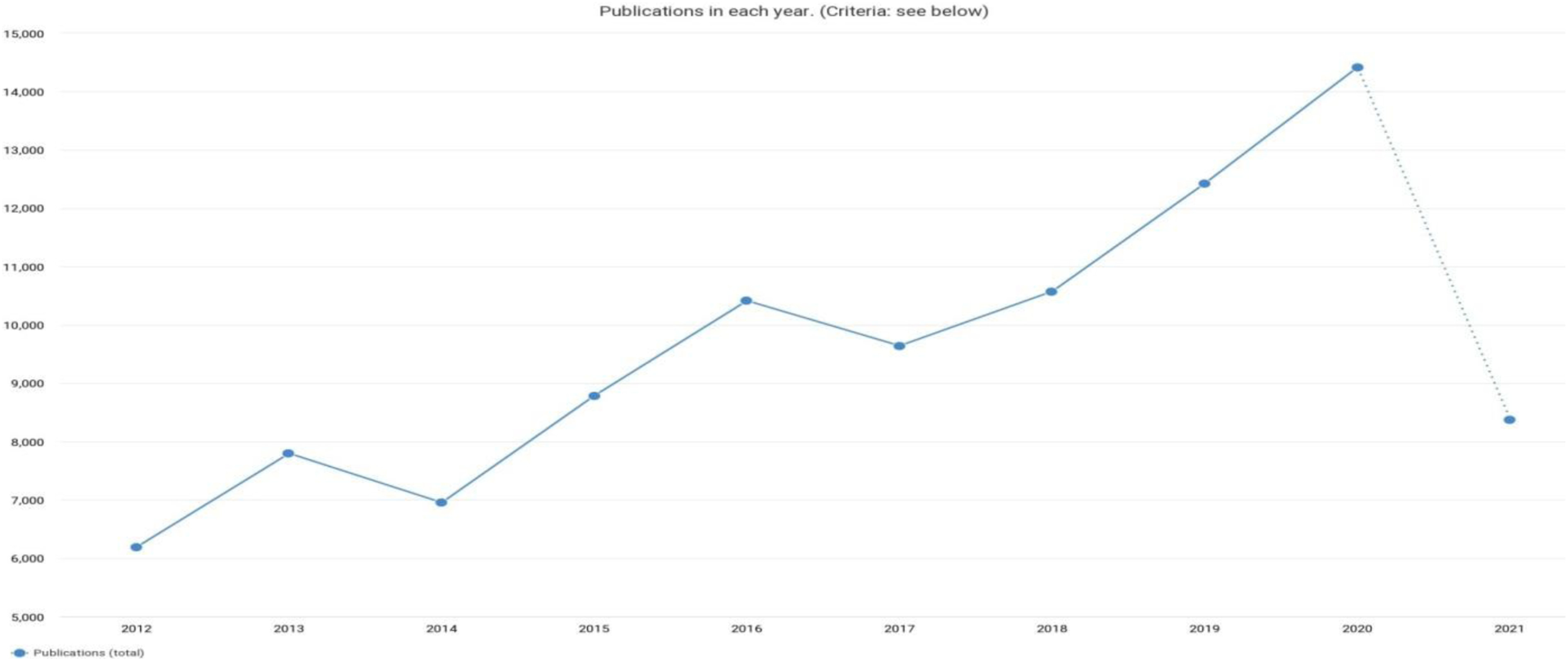
Figure 11 shows the schematic representation of articles published in CNTs from the year 2012 to 2020. The data is obtained from the diemensions.ai. From
Figure 11, it was clearly understood that the articles published in CNTs synthesis were kept on increasing by year by year. This graph represents the CNTs synthesized using the CVD process, this shows the importance CVD process for industrial scale-up. Also,
Table 4 shows the top 10 researchers who published articles in CNTs synthesis for the past decade.
Table 4 is composed of the name of the researcher and their respective affiliation, the number of publications, citations, and citation mean.
Carbon nanorings
Due to the research carried out on carbon nanotubes (CNTs), especially the synthesis of different allotropes of carbon nanomaterials, such as carbon nanorings,
56 carbon nanorods,
57 and carbon nanospheres.
58 Nanotechnology field is becoming more and more obvious. After CNTs, single-walled carbon nanorings (SWCNRs) and multi-walled carbon nanorings (MWCNRs) have been found to be the most interesting carbon nanostructures because they are considered the giants of all carbon structures and are used directly as nanoscale devices.
8 Recently, several research groups have reported the formation of modified CNTs in toroidal carbon tubes through post-treatment processes.
35,56,59 In most cases, the post-treatment process involves a chemical treatment to fold the CNT into a ring structure, which can change the basic properties of the nanotubes.
60Zhou. et. al. 2006,
61 synthesized SWCNRs in a floating catalyst chemical vapor deposition (FCCVD) process. FCCVD consists of a dual furnace configuration in, which the catalyst is placed in the first furnace and the substrate was placed in the second furnace at 1100°C. Song. et. al., (2006)
19 used the FCCVD process and ferrocene as a catalyst, SWCNRs was synthesized in a similar way at 1100° C. However, few investigators report the use of catalytic CVD
56,58,62,63 to synthesize CNRs. There is a lack of information on the characteristics of the catalyst particles that were used to synthesize CNRs, especially in the catalytic chemical vapor deposition (CCVD) process.
Recently, Venkatesan. et. al., (2018)
64 optimized the CCVD parameters to synthesize well-aligned multi-walled carbon nanotubes (MWCNTs) using Ni/Al
2O
3 as a catalyst material. It is believed, that CNT bundles can be grow abundantly using agglomerated catalyst particles.
Effect of CVD process parameters on CNRs growth
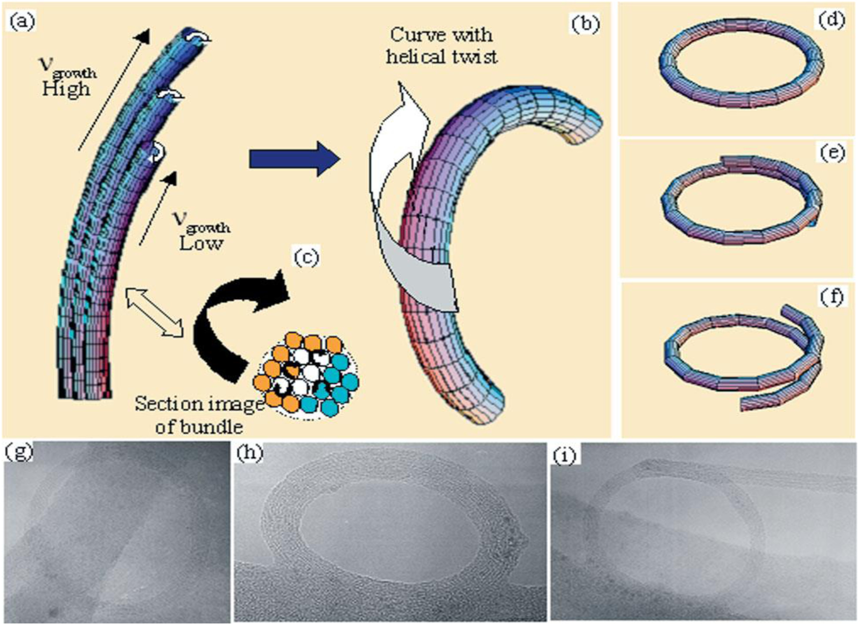
There is no much study reported on the effect of CVD process parameters on the structure of CNRs. Song. et. al., (2006)
19 synthesized CNRs using the CVD process. The author studied the growth process with respect to the experimental parameters to obtain optimal synthesis conditions. SWNT rings amount of growth was determined by the amount of sublimation catalyst, which can be adjusted by changing the sublimation temperature, with an increase in the sublimation temperature from 50 to 65°C, more of the catalyst is sublimed; and the samples tend to have proportionately more SWNTs with linear structure. Conversely, when the sublimation temperature is below 50°C, neither ring nor linear SWNT products are obtained. Meanwhile, author has been found that the reactant gas flow greatly influences the formation of SWNT rings. The optimum flow ranges from 200 to 600 sccm with the ratio of acetylene to argon varying from about 0.02 to 0.1 vol % (See
Figure 12). Further, they found that the quantity of SWNT rings obtained is also influenced by other experimental parameters, such as the reaction time and the growth temperature. Therefore, by adjusting these parameters, one can deposit SWNT rings onto different substrates with a wide range of densities, as demonstrated in
Figure 12.
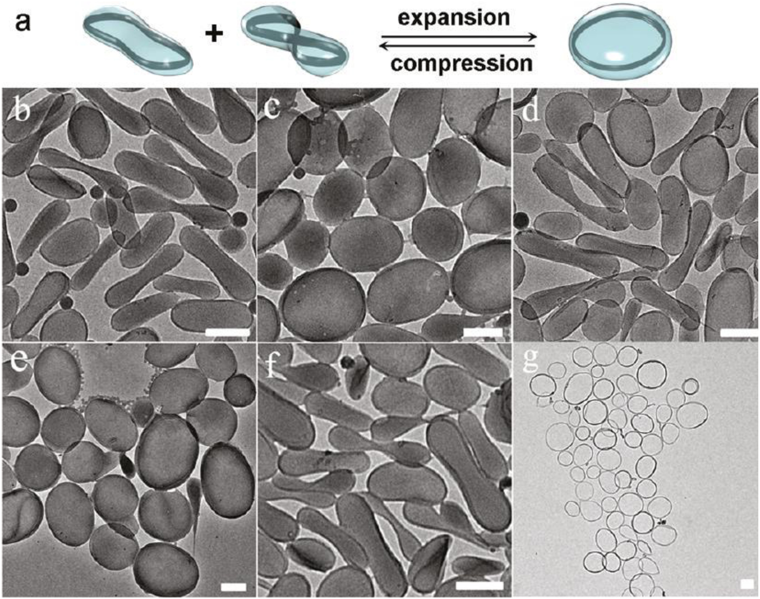
Chen. et. al. (2011)
58 used molecular dynamics (MD) simulation methods to study thermal stability and morphological changes of nanorings with different radii during temperature increase. Using the different initial C-C bond lengths of the chair carbon nanotubes, five metastable nanorings were generated. The stable structure of the two smallest nanorings has several twisted regions around the nanorings, and the deformation of the inner and outer walls occurs at the same temperature. For the three largest cases, the morphology of the nanoring in the top view shows a circle at 0 K. For a nanoring with a radius of 146 A° (350 units), the thermal deformation process is very similar to the two smaller cases. However, the temperature at which the thermal deformation starts is higher.
For the nanoring with ring radii of 165 A ° (400 units) and 185 A ° (450 units), the inner wall of the nanoring will be thermally deformed, and then the outer wall will be deformed at higher temperatures.
Figure 13 shows the changes of the local structure of the distorted area at different temperatures.
Impact of CNRs research
Figure 14 shows the schematic representation of articles published in CNRs from the year 2012 to 2020. The data are obtained from the diemensions.ai. From
Figure 14, it was clearly understood that the articles published in CNTs synthesis were drops after the year 2016. Also,
Table 5 shows the top 10 researchers who published articles in CNRs synthesis for the past decade.
Table 5 is composed of the name of the researcher and their respective affiliation, the number of publications, citations, and citation mean.
Carbon nanospheres
Zhang et. al. 2016
20 synthesized CNSs using a non-catalytic CVD process and reported the formation mechanism using CH
4 and H
2 as the precursor gas. Xu et. al. (2005)
16 synthesized CNSs using two different substrates such as kaolin-supported catalyst and ceramic plate via CVD process using C
2H
2 and reported that they synthesized two different kinds of carbon nanostructures, carbon nanotubes, and carbon spheres. Li et. al., (2016)
38 synthesized hollow carbon spheres and yolk-structured carbon spheres using metal catalyst-free CVD process using methane as the precursor gas.
Effect of CVD process parameters on CNSs
Zhang. et. al. (2016)
20 synthesized CNSs by non-catalytic chemical vapor deposition of natural gas/hydrogen mixtures. Author varied the deposition temperature from 1070 to 1200°C, the deposition temperature showed no significant effect on the sphere size and structure. The author revealed that with the increase of deposition pressure, the chance of collision of carbon sphere nuclei was increased. Hydrogen was likely to adsorb to the surface of carbon sphere nuclei and reduce the collision probability of carbon sphere nuclei. It was revealed that carbon nanospheres (50–100 nm) could be produced at 1150°C and 5 kPa with a gas mixture of natural gas/H
2=1/4.
Pol. et. al. (2006)
65 studied various hydrocarbons containing 5–14 carbon atoms (pentane, cyclohexane, camphorquinone, xylene, mesitylene, camphene, decahydronaphthalene, diphenylmethane, and anthracene) were dissociate under their autogenic pressure developed at 700°C to produce pure carbon materials (see
Figure 15). From all of the hydrocarbons, more than 99% pure carbon is obtained in spherical, filament- or egg-like microstructures.
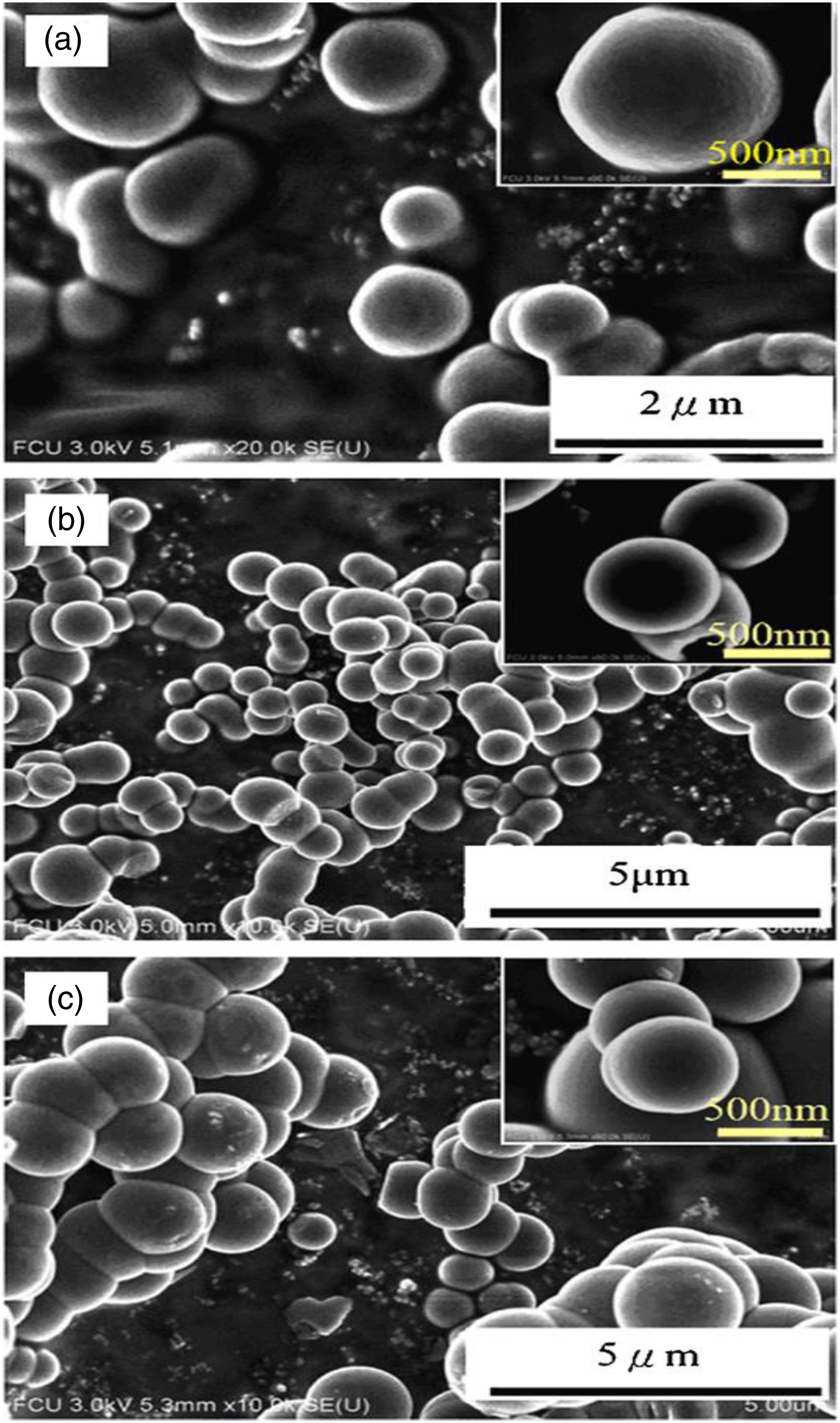
The key thing in the thermal dissociation of various hydrocarbons, followed by solidification under autogenic pressure, is the shape of products with micrometer dimensions, while the organometallic compounds yield nanometric products via a similar method. Specific systematic morphological, structural, and compositional analysis is presented for the products obtained from the thermal dissociation of diphenylmethane. Lee. et. al., (2011)
38 synthesized sub-micrometer carbon spheres successfully by catalytic CVD using novel catalyst on kaolin support. The author claiming that they reported for the first time that the non-magnetic metal (La, Nb, and Ti) complexes catalyzed the carbonization of C
2H
2 into carbon spheres. The author reveals that the favorable growth temperature falls between 720 and 810 C. The X-ray diffraction patterns of carbon spheres show graphitic structure with transition metal crystallites excluded. The diameters of solid-core carbon spheres using La, Nb, and Ti as catalyst were determined by TEM as 600–875, 425–1100, and 650–1250 nm, respectively (see
Figure 16). The acquired curves of magnetic susceptibility for Carbon spheres show background noises only, indicating no superconductivity and encapsulation of transition metal nanoparticles. The Raman spectra at room temperature showed a higher degree of graphitization for the La-catalyzed carbon spheres, based on the relative intensity of the feature peaks at 1325 cm
−1 and 1580 cm
−1. Finally, the author concluded that the CS-Ti and CS-La are two promising candidates for traditional and novel applications due to their comparable thermal and electrical conductivity to those of commercial carbon black.
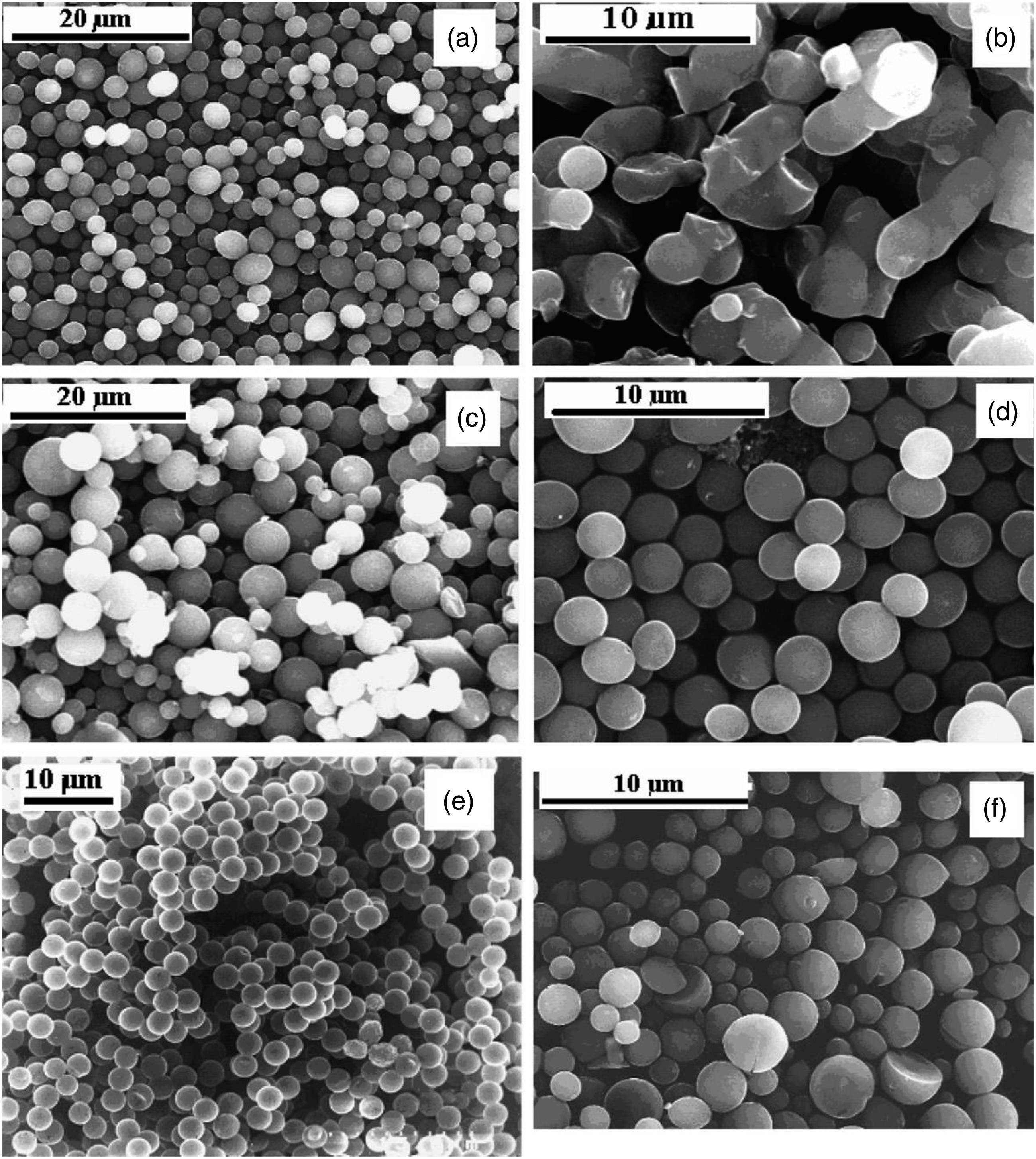
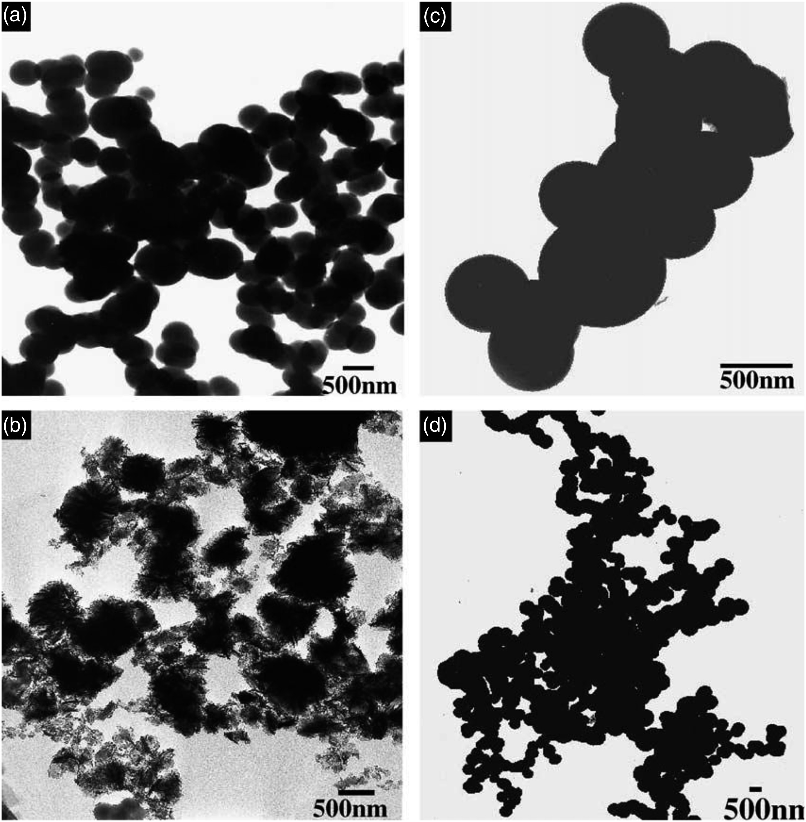
Miao. et. al., (2004)
66 synthesized carbon spheres with diameters in the range 400–2000 nm are by catalytic CVD in large quantities using kaolin-supported cobalt catalysts (see
Figure 17). Using this technique, one can optimize the size of the carbon spheres with the conditions of their report and with high yields produced within the temperature range 750–850°C
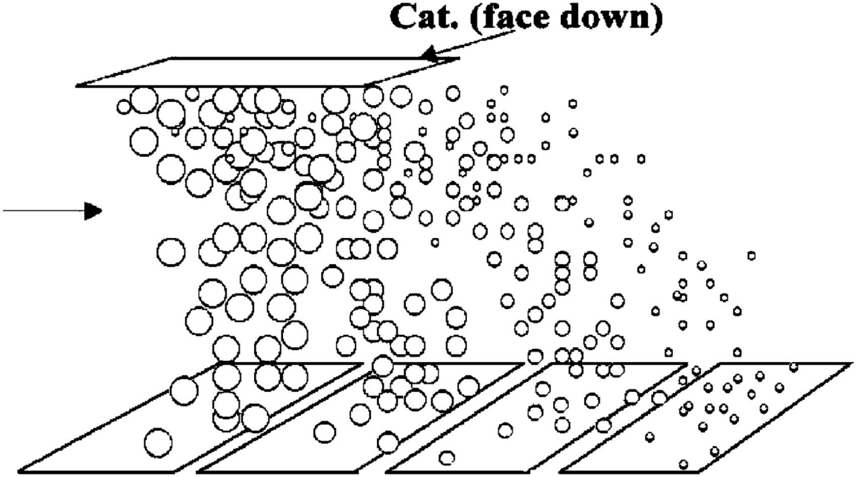
The Dysonian shape of ESR spectra indicates metallic nature for the carbon nanostructure. ESR and SQUID measurements indicate the existence of significant magnetization and indicate the possibility of using these materials for commercial magnetic applications. The highly inert and lightweight mechanical properties of these spheres give hope that they may be promising as lightweight materials for spacecraft applications. The author has depicted the entire synthesized step as a schematic representation as shown in
Figure 18.Impact of CNSs research
Figure 19 shows the schematic representation of articles published in CNSs from the year 2012 to 2020. The data are obtained from the diemensions.ai. From
Figure 19, it was clearly understood that the articles published in carbon spheres were increasing after the year 2016. Also,
Table 6 shows the top 10 researchers who have published articles in CNSs for the past decade.
Table 6 is composed of the name of the researcher and their respective affiliation, the number of publications, citations, and citation mean.
Summary and future scope
“Buckytubes are in high school now,” statement said by Rick Smalley, in 2000. After 20 years of research, researchers have discovered many allotropies of carbon like sphere and ring structures. The growth mechanisms of the CNTs were clearly understood from the literature survey. But the growth mechanisms of the spheres and rings were still in debate. The impact of research in allotropies of carbon nanostructures reveals that the publication of articles in rings and spheres (see
Figures 14 and
19) drastically decreased after 2016. But articles published on CNTs research keep on increasing, which is seen from
Figure 11. Researchers also claim that the CVD process was a viable technique to synthesis CNTs as compared to other synthesizing techniques like arc discharge and laser ablation. Many researchers have controlled the morphology of the CNTs like diameter and length. Authors also used statistical tools like response surface methodology to optimize the CVD process parameters to control the chemical and physical structure of CNTs.
67,68 Researchers also have optimized the CVD process parameters to increase the yield of the CNTs to use the CVD on an industrial scale. Catalysis is the seed of the CVD–CNT technique and it seems that researchers have used many transition metals to grow CNTs in the CVD process. Researchers have used transition metal catalysts like Ni, Cu, Co, Fe, and Al to grow CNTs via the CVD process. CNTs were successfully used in applications like hydrogen storage, electron emission, and drug delivery, reinforcement for composites.
69,70,71 On the other hand, there is no much research was undertaken in synthesizing spheres and rings. But spheres and rings are capable of performing better than CNTs structure in energy storage, and sensors.
Acknowledgements
The first author gratefully acknowledges the financial support provided by M/s. VB Ceramics Consultants (VBCC), Nehru Nagar Industrial Estate, Kottivakkam, Chennai-600041, and India through VBCRF (VBCERAMICS RESEARCH FELLOWSHIP). The first author grateful to the Dr K. Suresh Babu, Assistant Professor, Centre for Nano Sciences and Technology, Madanjeet School of Green Energy Technologies, Pondicherry University, for his fruitful discussions.